Arduino Obstacle Detection System
An ultrasonic proximity alarm on an Arduino UNO: the warning LED accelerates as an object closes in, and an IR remote drives the screens, units, and settings.
Six things have to happen at once on a chip that can only do one.
The brief was small: measure how far away something is and warn about it. The hard part is everything that has to be true at the same time. The sensor fires every 60 ms. The warning LED blinks at an interval that changes with the distance. The alarm LED blinks on its own schedule. The photoresistor is sampled every 100 ms. The button is debounced. The IR receiver is polled for a remote press that could arrive at any moment.
An Arduino UNO is one core at 16 MHz with no operating system, no threads, and no scheduler. Nothing here is computationally hard. The whole difficulty is that six independent schedules have to interleave on a processor that can only ever be doing one of them, and any one of them stalling is visible immediately — a stuttering LED, a remote press that gets dropped, a display that lags behind the sensor.
What the system has to do.
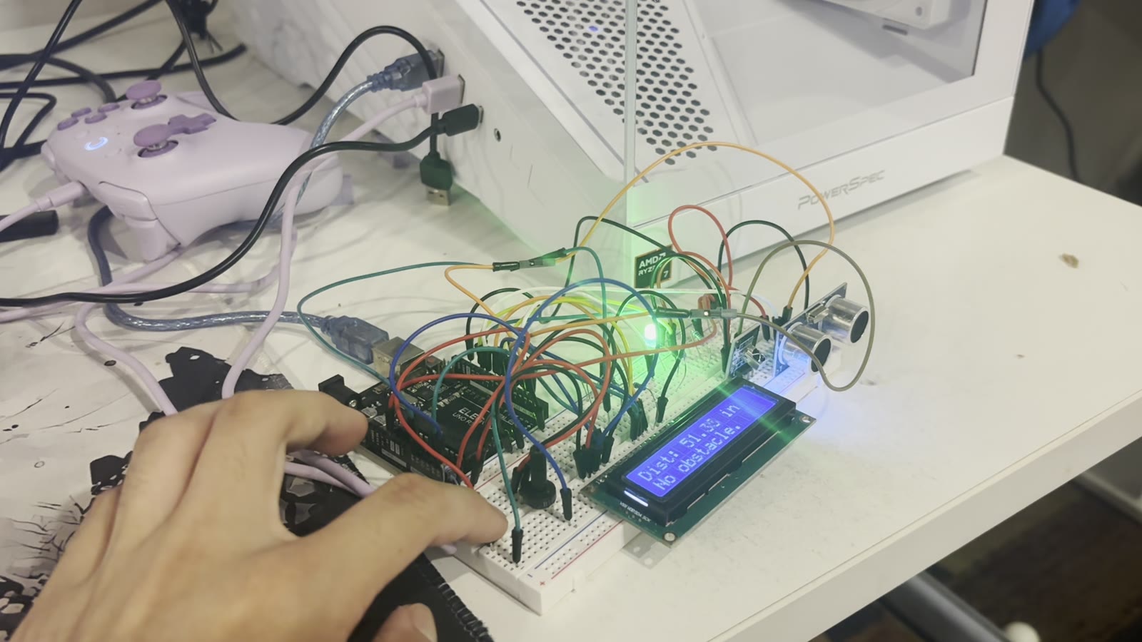
Continuous ultrasonic ranging with a readable output. Raw HC-SR04 samples jump several centimetres between readings, so the number on the display and the rate of the LED both have to come from something smoothed.
Proportional, not stepped. The warning LED's blink rate is derived from the live distance so it accelerates continuously as something approaches, and the alarm latches inside 10 cm rather than flickering on and off at the boundary.
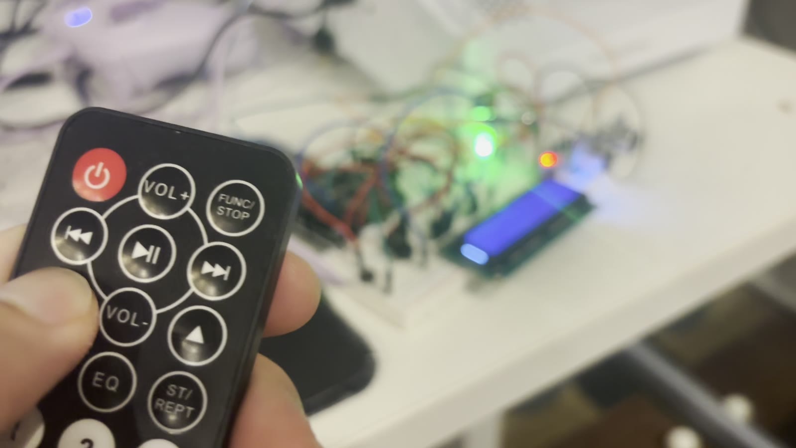
An IR remote and a physical button. Three LCD screens, a cm/inches toggle, a settings reset, and two independent ways to clear the alarm — all handled without the main loop ever waiting on any of them.
Everything runs on the board. There is no serial link to a computer in normal operation, no logging, and no way to read the history back — the display and the LEDs are the entire interface.
loop() is a scheduler, not a script.
The single rule the whole sketch is built on is that there is no delay() anywhere in loop(). Every pass reads millis() once into timeNow, and each subsystem owns a lastTime… timestamp and an interval and decides for itself whether it is due. They interleave without knowing about each other, and adding a seventh would mean adding one more timestamp rather than restructuring anything.
The ultrasonic sensor is the one piece that cannot be handled by polling alone. The obvious way to read an HC-SR04 is pulseIn(), which blocks until the echo comes back — at four metres that is over 23 ms of doing nothing, which at 60 ms intervals eats a third of the duty cycle and visibly stutters every LED on the board. So the echo pin gets a CHANGE interrupt instead. The handler does nothing but timestamp the rising and falling edges with micros() and set a volatile flag; loop() picks up the finished measurement whenever it next comes around.
Everything the display shows is derived, never stored. There is no model of the world beyond a smoothed distance, a lock flag, a screen index, and a unit. Which screen renders is decided at print time from lcdMode and isLocked, so the alarm can take over the display from anywhere without any of the other subsystems knowing it happened.
What one pass through the loop actually does.
Read the clock once
One millis() call at the top, compared against each subsystem's own timestamp. Anything not yet due is skipped in a single comparison, so a pass where nothing is scheduled costs almost nothing.
Fire whatever is due
Trigger the sensor, toggle an LED, sample the photoresistor, poll the IR receiver, read the button. Each one returns immediately — nothing in the body of the loop waits on hardware.
Pick up the interrupt's work
If the echo handler has set its flag, the raw pulse width is turned into a smoothed distance, which sets the blink rate, updates the display, and may latch the alarm.
From a 10-microsecond pulse to a blink rate.
The ranging path is the part with the most going on, and every step of it exists because the naive version of that step didn't hold up on the bench.
Trigger, and walk away
Every 60 ms the trigger pin is pulsed high for 10 µs. That is the only blocking wait in the sketch, via delayMicroseconds, and at 10 µs it is far below anything the rest of the board can notice.
Time the echo in an interrupt
A CHANGE interrupt on the echo pin fires twice — once on the rising edge, once on the falling. The handler records micros() into pulseInTimeBegin or pulseInTimeEnd and sets newDistanceAvailable. It does no arithmetic, no printing, and no digitalWrite, because an ISR that runs long delays everything else on the chip.
Convert, and reject the impossible
Back in the loop, the pulse width divided by 58 gives centimetres. Anything over 400 cm is outside what an HC-SR04 can actually resolve, so it is discarded and the previous reading is reused rather than letting a spurious echo reach the display.
Smooth it
An exponential moving average, previous * 0.6 + new * 0.4, weighted toward history. Raw readings jump by several centimetres between samples; at 16 refreshes a second that is unreadable on the LCD and, because the blink rate is computed from the same number, it turns into a visibly stuttering LED.
Turn distance into a rate
warningLEDDelay = distance * 4. One line, recomputed from the newest reading every time, which is what makes the LED accelerate smoothly instead of stepping between fixed speeds. It communicates distance without anyone reading the display.
Latch if it's close enough
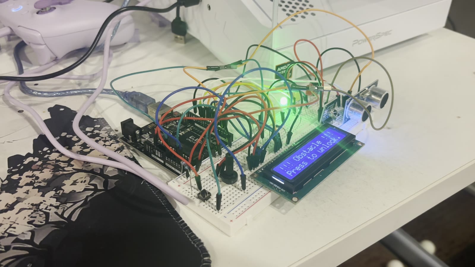
Under 10 cm the system locks: both LEDs move to a shared 500 ms blink, the display switches to the alarm message, and normal rendering stops until a button press or the remote's play button clears it.
Choices behind the interface.
What I chose, and what it cost.
Writing to EEPROM on every unit toggle
CostEEPROM cells are rated for around 100,000 writes. Nobody is going to press EQ that many times, so in practice this is free — but it is free by luck rather than by design, and the same pattern applied to something that changes often would wear a cell out. The correct version debounces the write, not just the press.
A latch that only polls the button while locked
CostThe button is read inside the isLocked branch, so it does nothing at any other time. That is deliberate — it has exactly one job — but it also means the input is unavailable for anything else without restructuring, and the pin sits idle 95% of the time.
Catching up missed intervals with += instead of resetting
CostAdvancing each timestamp by its interval keeps the schedule from drifting, which is the right call. It also means that if something ever did stall the loop, the missed ticks come back all at once instead of being dropped. Nothing in this sketch stalls, so the failure mode never fires — but it is a real one, and it is load-bearing that no ISR here does any work.
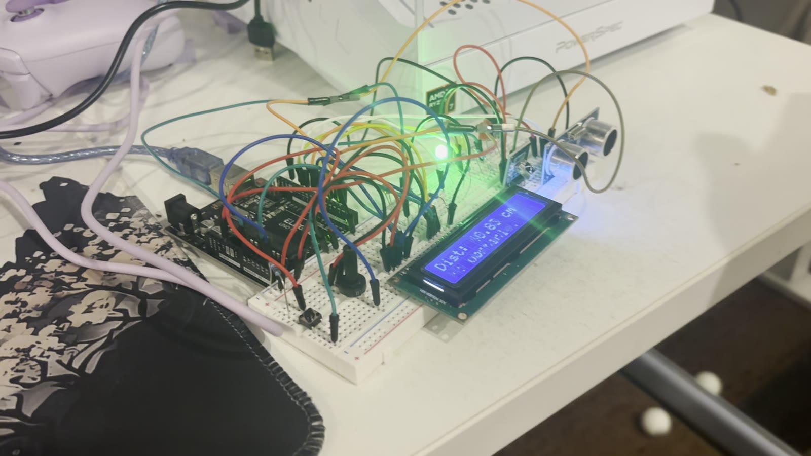
The LCD has no way to clear a single line. Print a shorter string over a longer one and the tail of the old string stays on screen — 129.68 cm followed by 51.03 cm renders as 51.03 cm cm, which reads like a corrupted reading rather than a display artifact. Every lcd.print in the sketch is padded with trailing spaces out to the full 16 characters for that reason. It is the least interesting line of code in the project and it was the one I spent the most time not understanding.
Where I'd take it.
Move the warning thresholds into EEPROM alongside the unit. 10 cm and 50 cm are compile-time constants right now, which means changing them means reflashing the board — and the settings screen already exists to edit them from the remote.
Log the alarms. The latch proves something came close, but not when or how close, and the board has no memory of it once cleared. A ring buffer of timestamped minimum distances in EEPROM would make the history readable from the LCD.
Use the photoresistor for more than the backlight. It already samples the room's luminosity every 100 ms and only drives one LED's brightness; the same reading could dim the LCD at night, or gate the alarm so it doesn't fire in a dark room nobody is in.